
GCR06 - reactive power controller
We will be happy to advise you:
GCR06 - reactive power controller
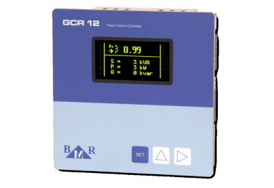
The power factor controllers GCR06 and GCR12 combine features and functions of the power factor controller and the multifunction monitoring instrument. Thanks to the graphic OLED (organic light emitting diode) display, all information is shown at the ...
The power factor controllers GCR06 and GCR12 combine features and functions of the power factor controller and the multifunction monitoring instrument. Thanks to the graphic OLED (organic light emitting diode) display, all information is shown at the same time for a faster overview and easy understanding about the PFC and grid situation. GCR controllers are designed for LV and MV application as well as for dynamic (fast) and hybrid thyristor power factor compensations.
show more
Order number: GCR06